 Somerled
LED Tester 2.0
$14.95–$34.95
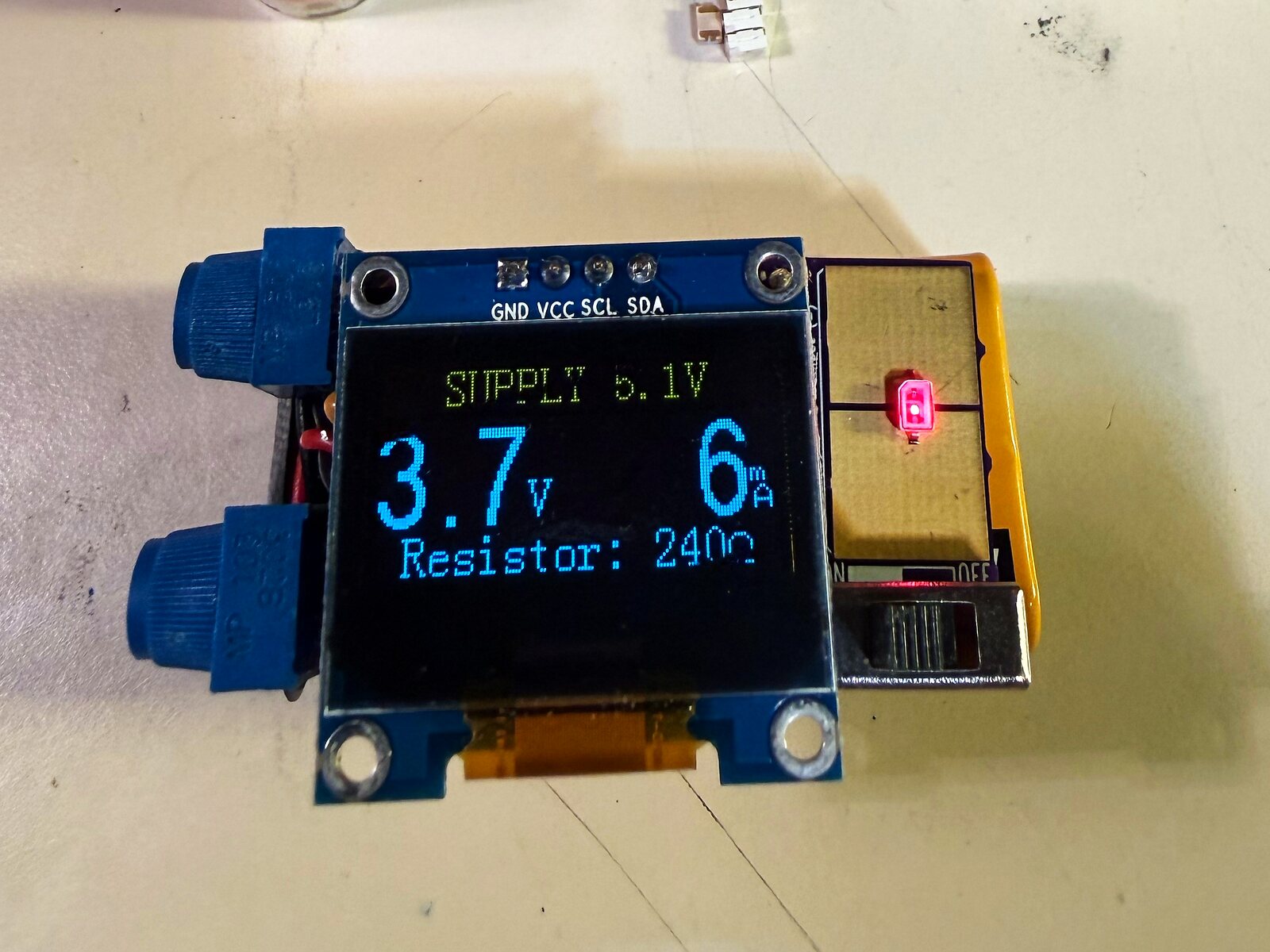
A current-limited LED tester that, given the applied voltage, tells you the resistor value for a set current. Four versions, from the no-display basic board to OLED and LCD readouts.
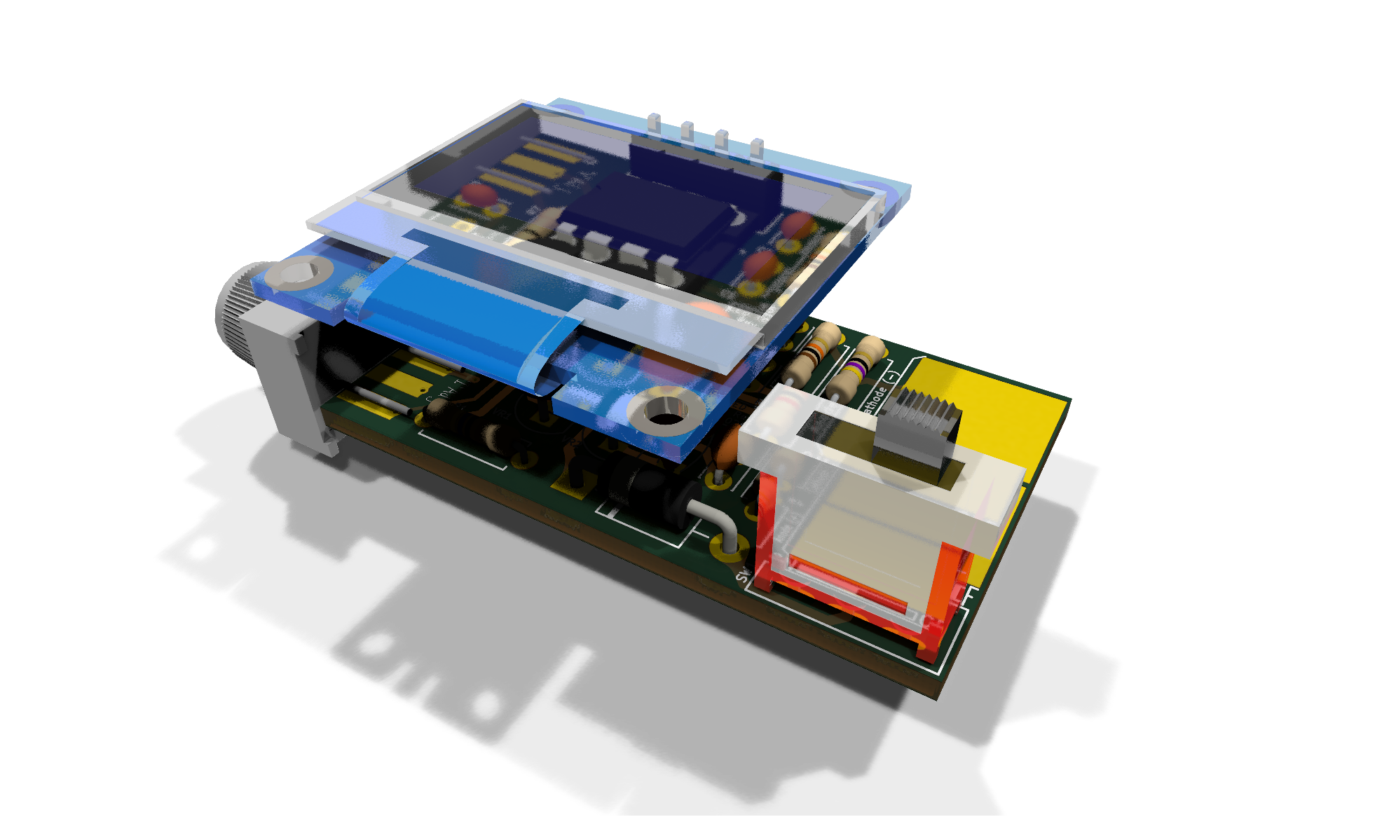
LED Tester 2.0: know the resistor before you solder
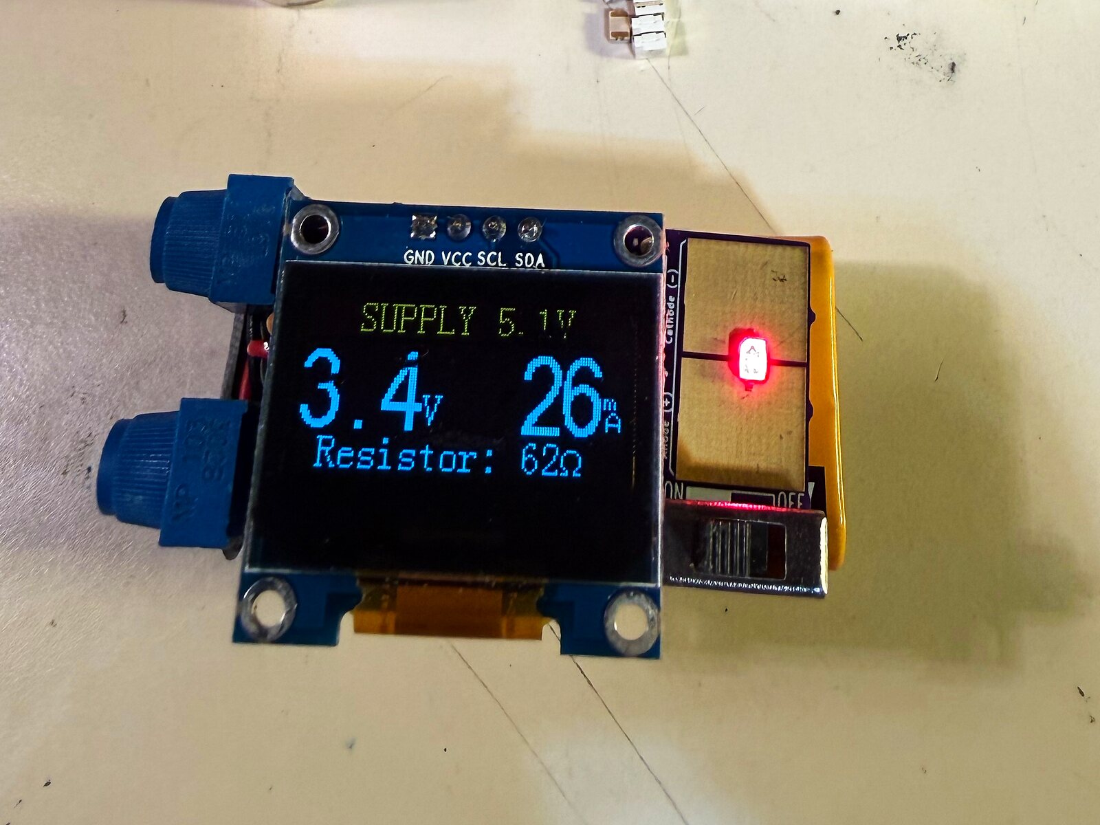
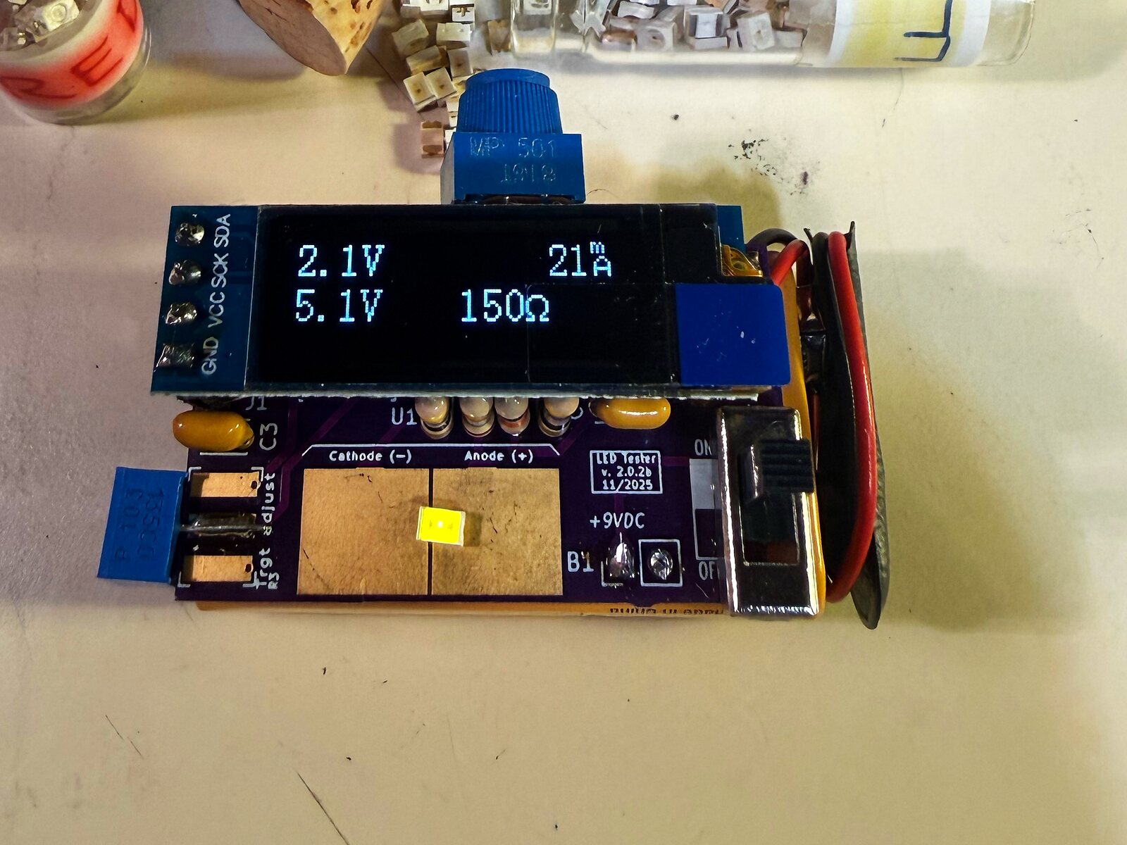
LED Tester 2.0 is a current-limited tester for LEDs. Touch an LED to the test pads, set the voltage you plan to run it from, and the tester gives you the resistor value for a set current. No more guessing or burnt-out LEDs.
- Current-limited test supply built on an LM317L regulator (VR1: onsemi LM317LZG or ST LM317LZ), so the LED under test is protected
- Measures the LED’s forward voltage with the microcontroller’s ADC
- Target-voltage dial: set the supply you’ll actually use (0–9.46 V full range on the OLED builds)
- Computes the series resistor for that voltage and current
- Adjustable test current, about 2.3 mA to 27 mA, set with the R2 knob (1.25 V / (47 Ω + 0–500 Ω)), same as v1.1
- 9 V battery powered, with an on/off switch; 9 V battery snap included in all kits (9 V battery not included)
- Through-hole parts: the ATtiny sits in a DIP socket (included in the kit); TO-92 regulators
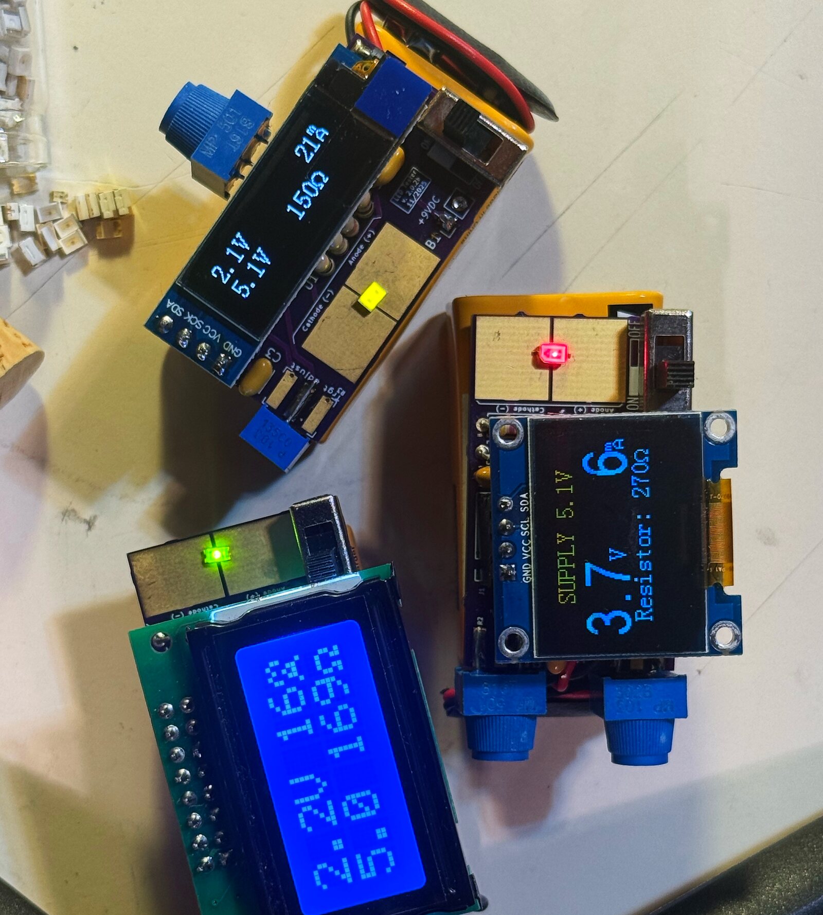
Four versions
| LED Tester v1.1A Basic | LED Tester v2.0 · LCD 0802 · Rev D | LED Tester v2.1 · OLED 128×64 · Rev D | LED Tester v2.1 · OLED 128×32 · Rev D | |
|---|---|---|---|---|
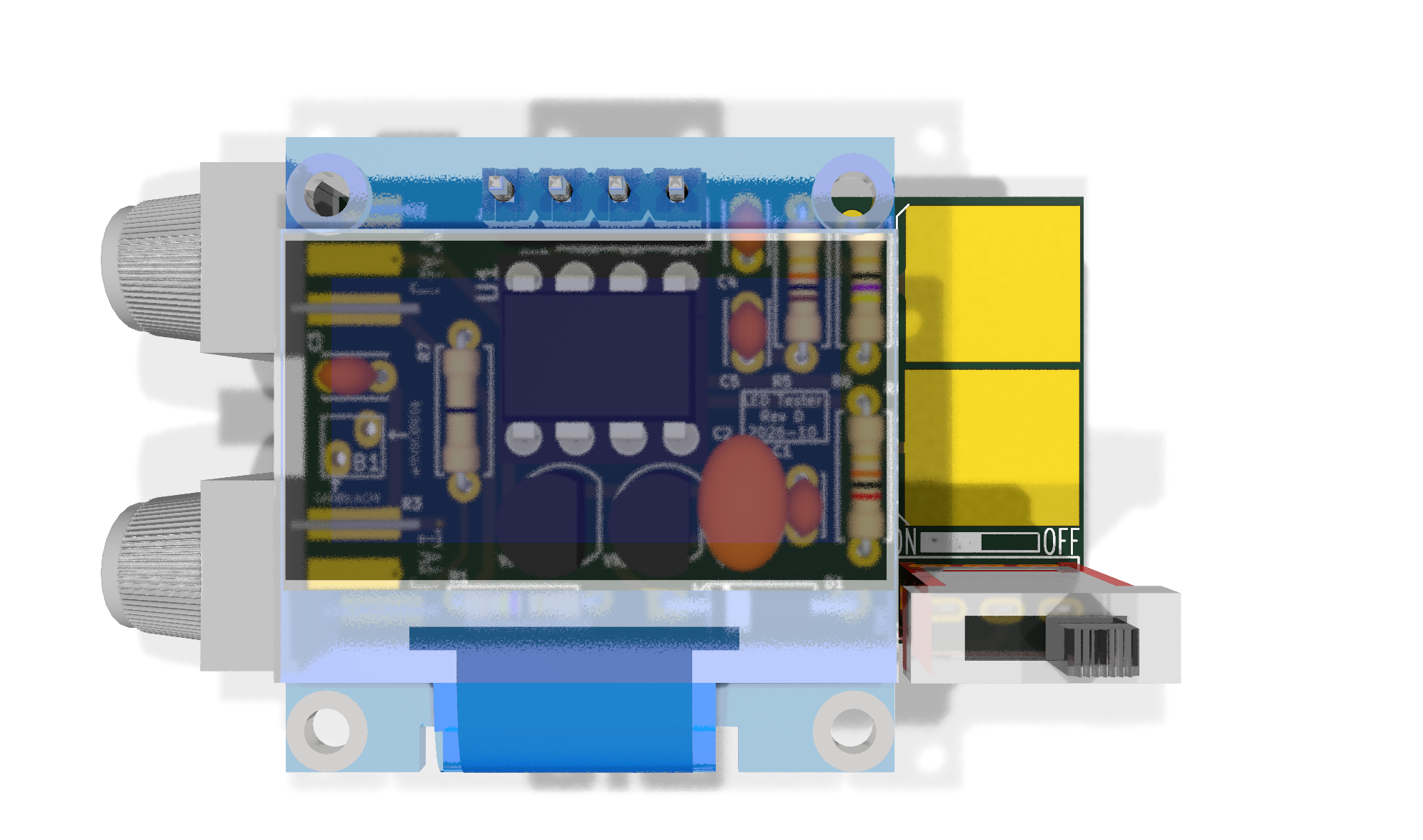
| Display | None | 8×2 character LCD (0802) | 128×64 OLED | 128×32 OLED |
| Microcontroller | None | ATtiny84A (DIP-14 socket included) | ATtiny85 (DIP-8 socket included) | ATtiny85 (DIP-8 socket included) |
| Logic supply | n/a | 5 V (LM2931AZ-5.0) | 3.3 V (L78L33) | 3.3 V (L78L33) |
| LED current source | LM317L | LM317L (LM317LZG / LM317LZ) | LM317L (LM317LZG / LM317LZ) | LM317L (LM317LZG / LM317LZ) |
| Test current | 2.3–27 mA (R2 knob) | 2.3–27 mA (R2 knob) | 2.3–27 mA (R2 knob) | 2.3–27 mA (R2 knob) |
| Board size | 1.700 × 1.000 in (43.2 × 25.4 mm) | 1.850 × 1.000 in (47.0 × 25.4 mm); display overhangs bottom edge | 1.625 × 0.975 in (41.3 × 24.8 mm) | 1.630 × 0.915 in (41.4 × 23.2 mm) |
| Power | 9 V battery | 9 V battery | 9 V battery | 9 V battery |
| Readout | Your multimeter (V and mA test loops) | Resistor value on LCD | Resistor value on OLED | Resistor value on OLED |
| Kit price | $14.95 | $34.95 | $29.95 | $27.95 |
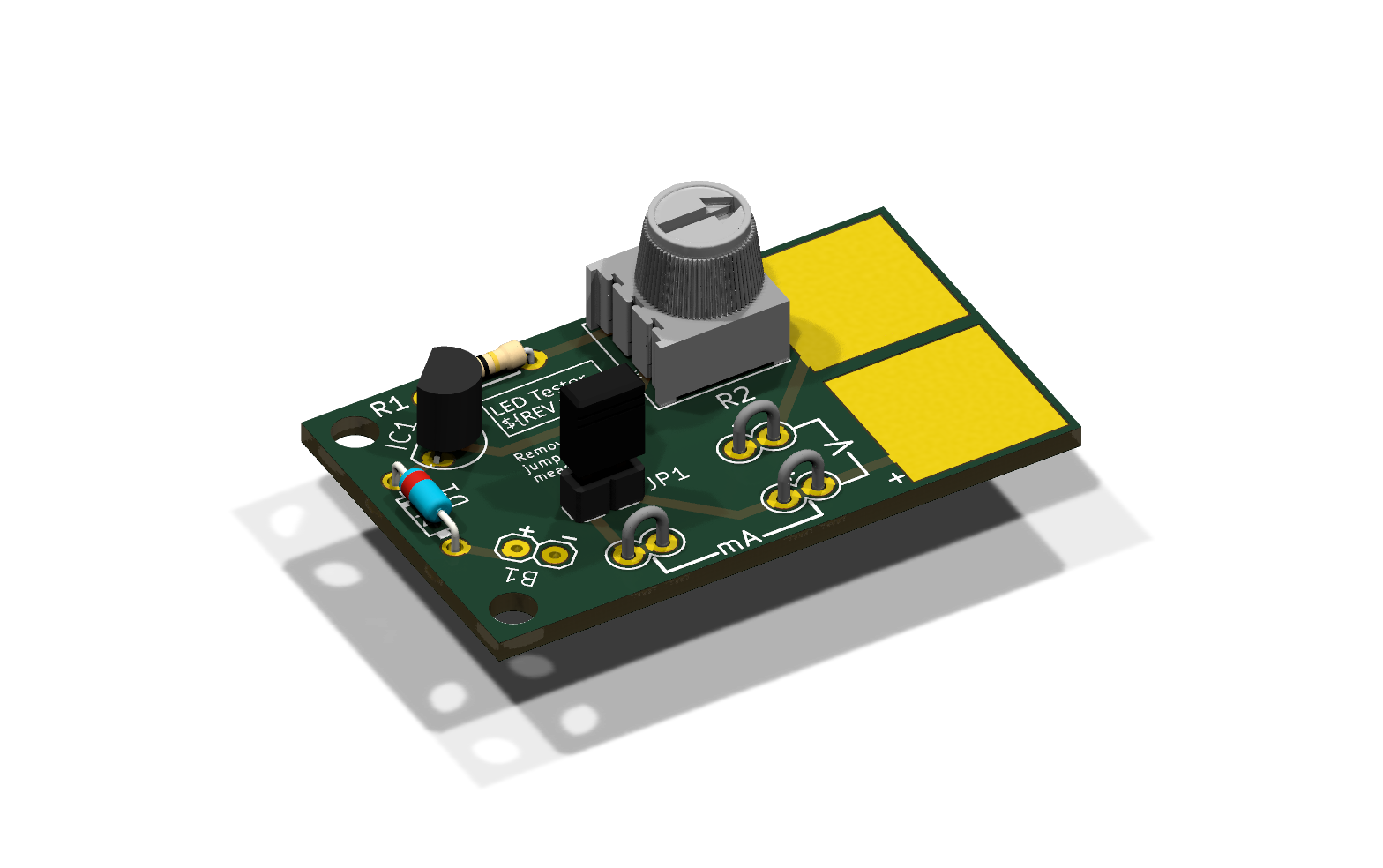
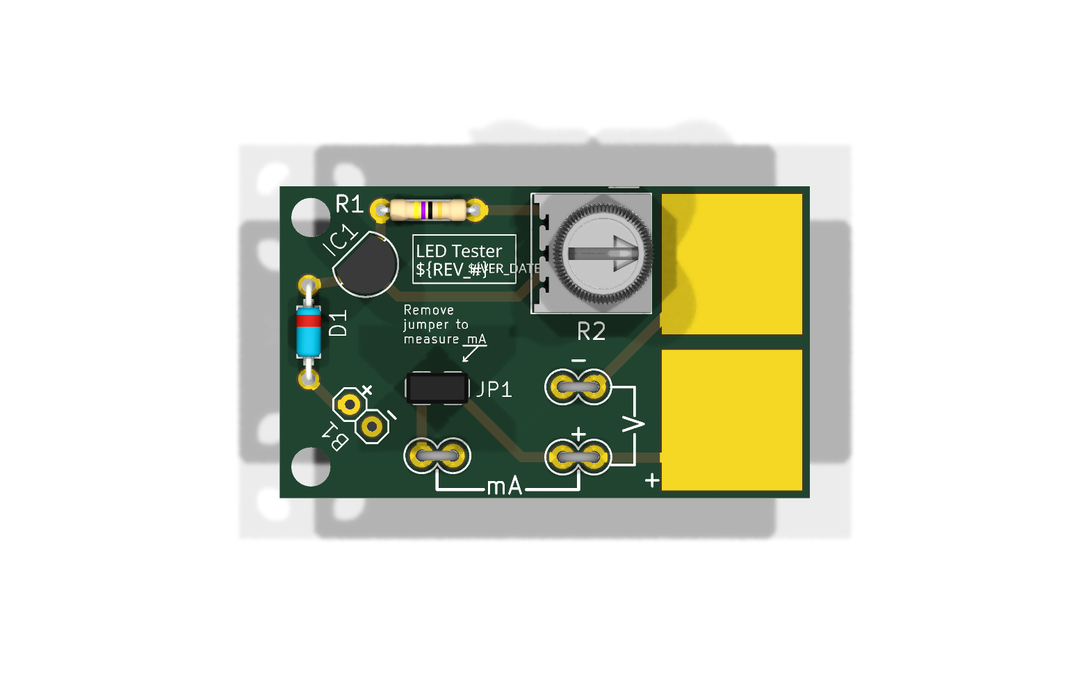
v1.1 Basic details
- No display, no microcontroller: read the LED’s forward voltage with your own multimeter at the V test loops (TP1/TP2), and the LED current at the mA test loops (TP3/TP2) with jumper JP1 removed
- Adjustable LED current, about 2.3 mA to 27 mA, via the 500 Ω trimmer R2 (clockwise = more current)
- 1N5817 reverse-battery protection
- No power switch needed: standby draw is practically zero
- Board size: 1.700 × 1.000 in (43.2 × 25.4 mm)
- 9 V battery snap included; 9 V battery not included
Which one?
Want the simplest possible build? Start with v1.1. Want the resistor value worked out for you? Pick one of the display versions: the 0802 LCD for a chunky character readout, or the OLED boards for a crisp graphic display.
What’s included
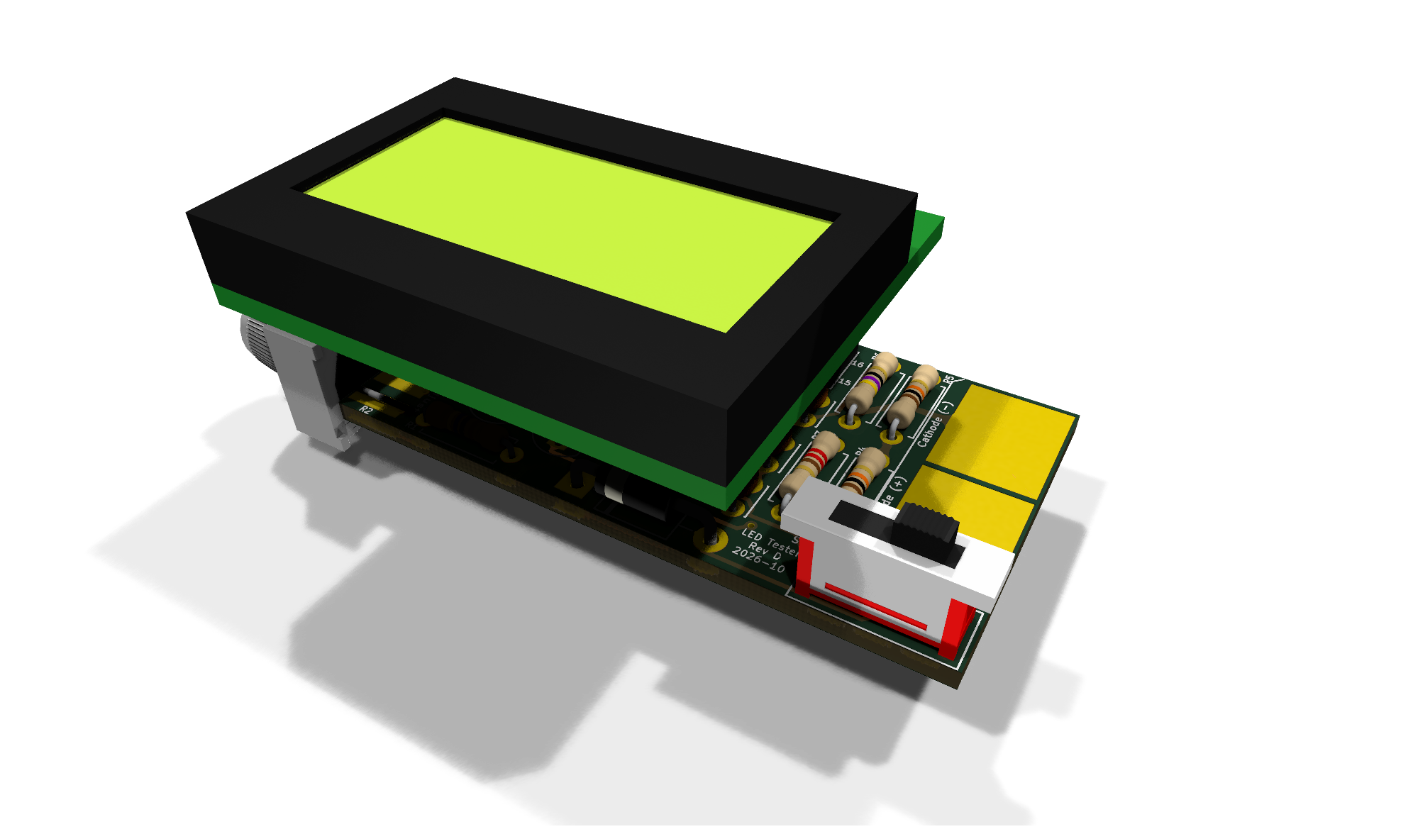
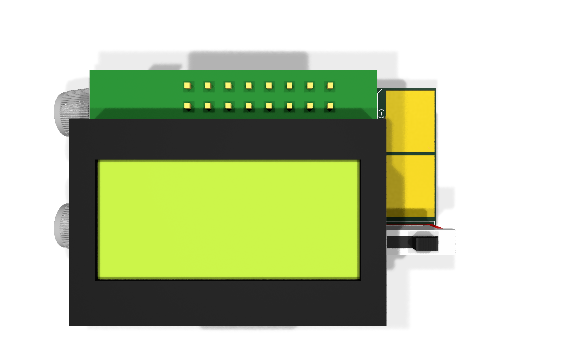
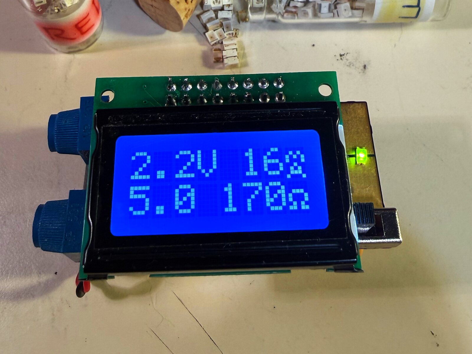
LED Tester v2.0 · LCD 0802 · Rev D ($34.95)
PCB; 47 Ω ×2, 10 kΩ ×2, 220 Ω resistors (⅛ W); 5 kΩ contrast trimmer; 1N5817; 0.1 µF ×4; 47 µF 6.3 V electrolytic (4 mm); LM317L; LM2931AZ-5.0; 500 Ω and 10 kΩ Bourns 3386F trimmers with knobs; 14-pin DIP socket; pre-programmed ATtiny84A; slide switch; 2×8 female and male headers; 8×2 backlit LCD; 9 V battery snap
LED Tester v2.1 · OLED 128×64 · Rev D ($29.95)
PCB; 47 Ω ×2, 20 kΩ, 10 kΩ resistors, 0 Ω link; 1N5817; 0.1 µF ×4; 1 µF tantalum; LM317L; 78L33; 500 Ω and 10 kΩ Bourns 3386F trimmers; 8-pin DIP socket; pre-programmed ATtiny85; slide switch; 4-pin female header; 0.96 in 128×64 I2C OLED; 9 V battery snap
LED Tester v2.1 · OLED 128×32 · Rev D ($27.95)
PCB; 47 Ω ×2, 22 kΩ, 12 kΩ resistors, 0 Ω link; 1N5817; 0.1 µF ×4; 1 µF tantalum; LM317L; 78L33; 500 Ω and 10 kΩ Bourns 3386F trimmers; 8-pin DIP socket; pre-programmed ATtiny85; slide switch; 4-pin female header; 0.91 in 128×32 I2C OLED; 9 V battery snap
- v1.1A Basic ($14.95): see the v1.1 details above; 9 V battery snap included
- All resistors are ⅛ W, 5%.
- You supply: a 9 V battery (not included in any kit)
Build guide / interactive parts list
Assembly manuals and interactive placement guides:
- v1.1 Basic: Manual (PDF) · Placement guide (iBOM)
- v2.0 LCD 0802: Manual (PDF) · Placement guide (iBOM)
- v2.1 OLED 128×64: Manual (PDF) · Placement guide (iBOM)
- v2.1 OLED 128×32: Manual (PDF) · Placement guide (iBOM)
More build help is on the Support page.
Credits
Original LED tester concept and trim pot selection: David Cook, Robot Room (robotroom.com). Thanks, David.
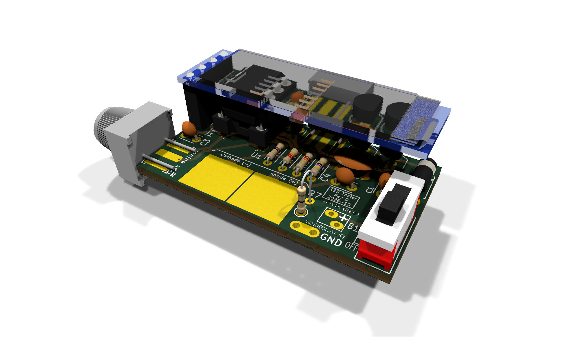
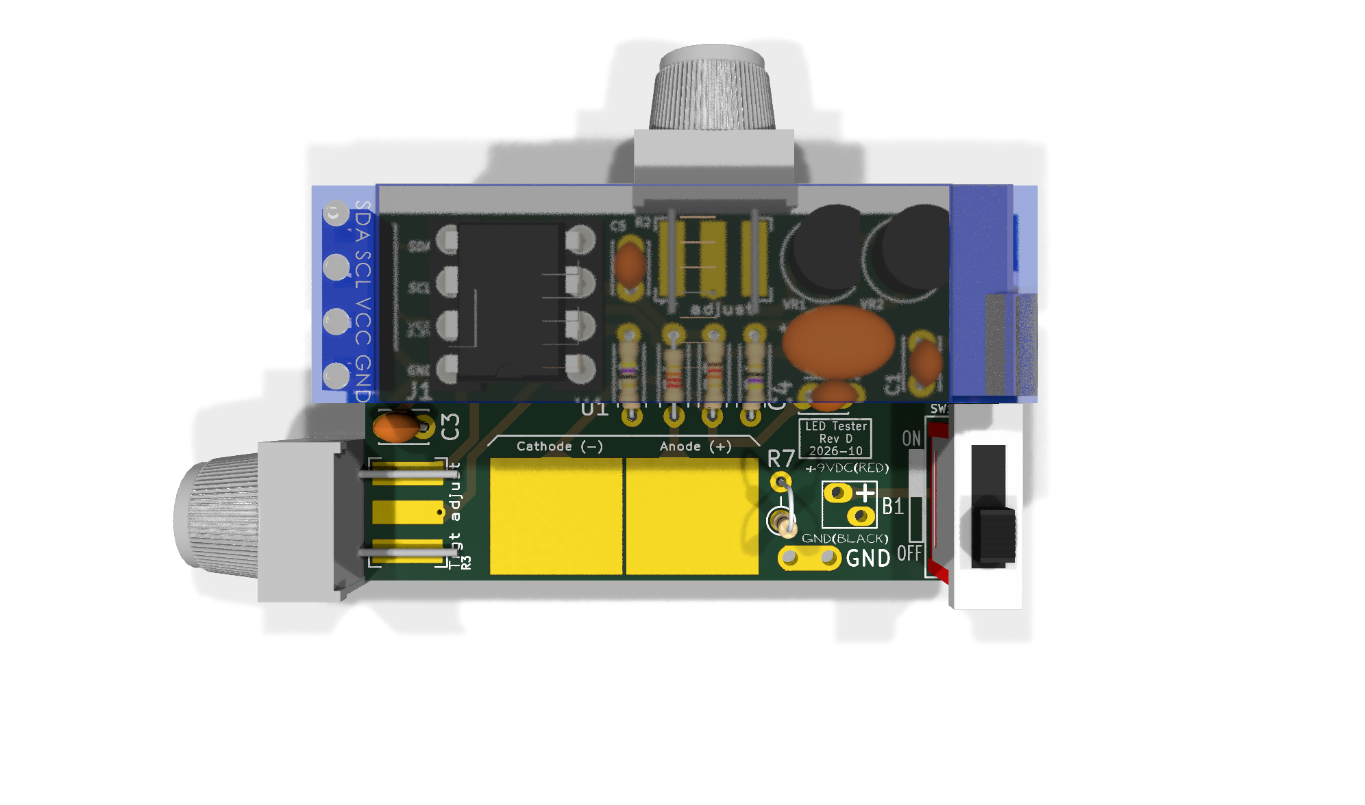
Board & product views